- Top Results
- Bosch Building Technologies
- Security and Safety Knowledge
- Fire
- How-to: Map Analog Outputs
How-to: Map Analog Outputs
- Subscribe to RSS Feed
- Bookmark
- Subscribe
- Printer Friendly Page
- Report Inappropriate Content
Question:
Can an input device on one loop card trip an output device on a different loop card or network analog panel?
Answer:
Yes, it is possible to map an input device of one loop card to trip an output device on the same or different loop card on the same networked analog system.
Instructions on how to program the outputs below.
Zone mapping
The control panel supports a flexible system to map input points to outputs. The system
defaults so that all NAC outputs are activated by a fire alarm. By programming output zones,
you can create almost any output activation scheme, such as "floor above and floor below"
activation or conditional elevator recall.
Input points: Smoke detectors, pull stations, and so on
Zone: A group of input points (zones 1 to 225 are configurable, 226 to 234
are activated automatically)
Outputs: Notification Appliance Circuits (NACs) such as bells, strobes, and
relays
Zone mapping on a networked system:
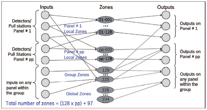
– For each panel on the network there are 128 local zones (pp-001 to pp-128, where pp =
the panel ID). Local zones are used to assign inputs and outputs specific to a device at
that zone address and to that panel.
– Each network also has 97 grouped zones (129 to 225). Grouped zone addresses allow
inputs and outputs to be assigned to multiple panels within a network so that the inputs
and outputs of each panel in the grouped zone can be connected to any of the panels in
the network.
– Each network also has 9 global zones (226 to 234). Global zones have preset inputs
based on device types, but their outputs can be defined and apply to the entire network.
– For local zones and group zones, up to 5 zones per input and 5 zones per output can be
mapped. More specifically, an input can be mapped to local zones on any panel within the
network or to group zones. The outputs from a local zone (1-128) can be mapped only to
the panel that zone is connected to, but the output from group zones (129-225) can be
mapped to any panel within the network.
Mapping principles:
– Inputs activate zones, and zones activate outputs.
– Input points can be assigned to up to five local or group zones. Therefore, each input can
activate up to five zones; however, any number of inputs can be mapped to the same
zone.
– Up to five local, group, and/or global zones can be assigned to each output (except the
FAA‑325‑B6S Analog Sounder Base which can be assigned to only one zone).
– Zones 1 to 225 are available for the installer to program.
– Zones 226 to 234 are global zones and are hard-coded to pre-assigned conditions. They
are automatically activated by inputs if a special condition occurs or the panel is in a
processing sequence (See the following two figures). It is not possible to assign an input
point to any global zone.
– An output can be assigned to a global zone so that it will be activated upon the
corresponding special condition. For example, any input that is configured as a "Fire
Auto" type activates Zone 226 when it is alarmed. Any output driven by Zone 226
activates when any “Fire Auto” type point is alarmed.
For how inputs control zones and zones control outputs in a network, see the following figure.
Network input-output mapping

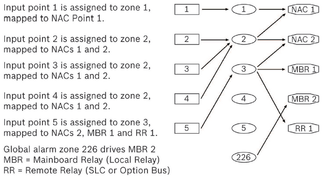
For how inputs control zones and zones control outputs in a stand-alone panel, see the
following figure.
Stand-alone panel zone mapping

For a list of all global zones on the panel (each has a unique number), see the following table.
Global Zone Number Condition Activating Zone
Pre-assigned zones
226 Global fire alarm
227 Global trouble
228 Global supervisory
229 Alarm verification (verification period)
230 Pre-signal (waiting for reset)
231 Positive Alarm Sequence (waiting for ACK or reset)
232 Panel is resetting
233 Global gas alarm
234 Global waterflow
In some cases if a relay output is assigned to a certain global zone, other assigned zones are
ignored:
– Mainboard relay 1: If assigned to the global alarm zone, other assigned zones are ignored.
The relay reacts only to the global alarm zone.
– Mainboard relay 2: If assigned to the global trouble zone, other assigned zones are
ignored. The relay reacts only to the global trouble zone.
– Mainboard relay 3: If assigned to the global supervisory zone, other assigned zones are
ignored. The relay reacts only to the global supervisory zone.
Outputs
is active if any zone to which the output is assigned is activated. An output which is assigned
to multiple zones can be considered as inactive only when all associated zones are inactive.
NAC pattern assignment
Every zone is assigned to one NAC pattern. When the zone NAC pattern is set to default, the
device NAC pattern is used. In case of a device activation by address, the device NAC pattern
is used. When a device is activated by a zone activation command, the NAC activates with the
assigned zone pattern (Steady, Pulsing, or Temporal Code 3, for global gas alarm also
Temporal Code 4). See the following table.
NAC pattern assignment

Counting zones
All local or group zones have the “Counting Zones” option. If this option is enabled, a local or
group zone becomes a counting zone.
Otherwise, it is a non-counting zone which is activated as soon as an input point assigned to
this zone is activated. If multiple points (can be from different panels if networked) are
assigned to a single zone, only when all the points are inactive is the zone considered as
inactive; thus, associated outputs can be deactivated.
A counting zone is considered active only when two or more input points assigned to that
zone are active. It is not allowed to assign an input point programmed with any delayed point
features (including PAS, Pre-signal, alarm verification, and PAS@day or
alarmverification@night) to a counting zone.
Still looking for something?
- Top Results