- Top Results
See all results
- Bosch Building Technologies
- Security and Safety Knowledge
- Fire
- How to configure the FPD-7024 for various network reporting options.
Turn on suggestions
Auto-suggest helps you quickly narrow down your search results by suggesting possible matches as you type.
Showing results for
How to configure the FPD-7024 for various network reporting options.
Options
- Subscribe to RSS Feed
- Bookmark
- Subscribe
- Printer Friendly Page
- Report Inappropriate Content
FPD-7024 Network Reporting Scenarios
- Notes:
- Firmware version 1.03 and earlier: Use option bus address 250 for the network communicator.
- Firmware version 1.06 and newer: Use option bus address 250 or 134 for the network communicator.
- Option Bus address 250 is used for connection to Remote Programming Software. When both Ethernet and Cellular network communicators are used, set the Ethernet communicator to address 250 to minimize cellular data usage.
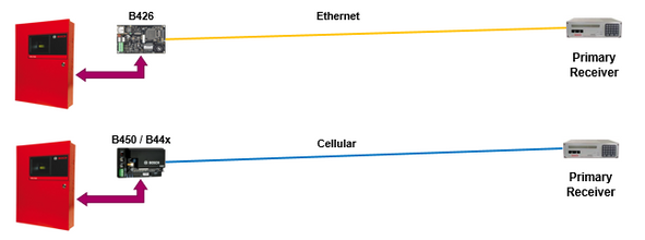
Single network communicator reporting to a single receiver.
- Compatible with firmware versions 1.03 or 1.06.
- Enter configuration settings for account 1 only. Account #2 remains empty.
- Set all reported events in Report Steering as: Phone/IP1 Only.
- Configure the network communicator for Option Bus address 250 (switch=9) to provide support for Remote Programming Software connections.
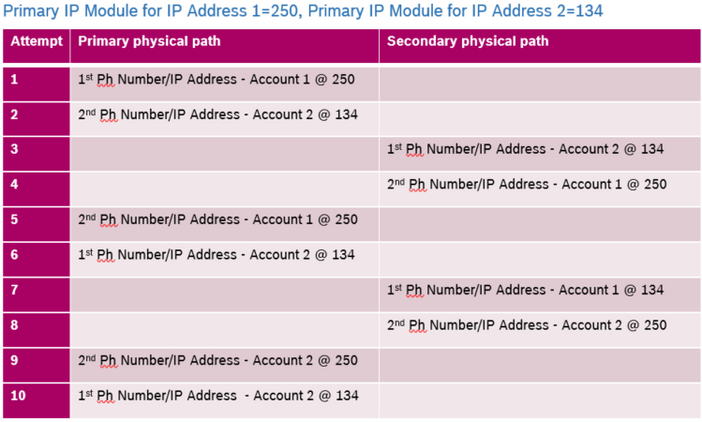
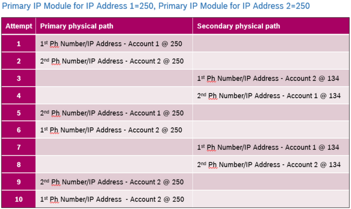
Communication Attempt Scenarios when using two IP Communicators.
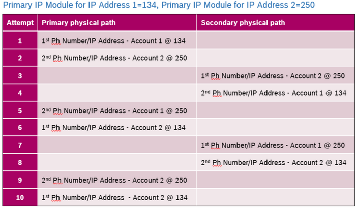
The version 1.06 FPD-7024 can support 2 network communicators addressed as 250 and 134. The order of communication attempts to Central Station is determined by the setting of: Primary IP Module for Address 1 and Primary IP Module for Address 2. The charts below describe the order of communication attempts.
Primary and backup network communicators reporting to a single receiver using one IP address.
- Requires firmware version 1.06 or greater. Provides redundant communicators to a single receiver with only one IP address.
- Enter configuration settings for account 1 only. Account #2 remains empty.
- Set all reported events in Report Steering as: Phone/IP1 Only.
- Configure the Ethernet communicator for Option Bus address 250 (switch=9) to provide support for Remote Programming Software connections to minimize cellular data usage.
Two network communicators to one receiver using two IP addresses (ver1.06).
- Requires firmware version 1.06 or greater. Provides redundant communicators to a single receiver with two available IP addresses.
- Use both accounts with a different IP address in each account.
- Each account may be configured with a different supervision time (i.e. Ethernet at 1 hour and Cellular at 24 hours for reduced network data usage).
- Set all reported events in Report Steering as: Phone/IP2 Backup or Phone/IP 1 and 2.
- Select the more stable or low cost network module as the primary IP module.
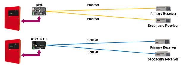
Single network module to two receivers (ver1.03 and 1.06):
- Compatible with firmware versions 1.03 or 1.06.
- If account 1 and 2 use different IP addresses, each account may use the same port number.
- If account 1 and 2 both use the same IP address the port numbers must be different.
- Each account may be configured with a different supervision time.
FPD-7024 Two network modules to Two receivers (ver1.03 and 1.06):
- Compatible with firmware versions 1.03 or 1.06.
- If account 1 and 2 use different IP addresses, each account may use the same port number.
- If account 1 and 2 both use the same IP address the port numbers must be different.
- Each account may be configured with a different supervision time (i.e. Ethernet at 1 hour and Cellular at 24 hours for reduced network data usage).
- Select the more stable or low cost network module as the primary IP module.
Communication Attempt Scenarios when using two IP Communicators.
The version 1.06 FPD-7024 will support 2 network communicators addressed as 250 and 134. The order of communication attempts to Central Station is determined by the setting of: Primary IP Module for Address 1 and Primary IP Module for Address 2. The charts below describe the order of communication attempts.
Rate this article:
Still looking for something?
- Top Results
See all results
