- Top Results
- Bosch Building Technologies
- Security and Safety Knowledge
- Security: Intrusion
- How to program Point Profiles or Indexes and how to enable points in G Series or B-Panels
How to program Point Profiles or Indexes and how to enable points in G Series or B-Panels
- Subscribe to RSS Feed
- Bookmark
- Subscribe
- Printer Friendly Page
- Report Inappropriate Content
What are Point Profiles or Point Indexes and how are they used?
- ‘Point Profiles’ or Point Indexes’ are sets of parameters which define how the panel will behave when a point becomes faulted. Point Indexes were re-named Point Profiles with the release of B8512G/B9512G & B-Series panels however either name refers to the same set of parameters.
- All points which generate the same panel behavior are assigned the same profile. For example, all perimeter doors that generate an instant alarm use the same Perimeter Instant profile. An additional Perimeter Instant profile is configured only when a separate group of points behave slightly differently. For example some doors generate a watch tone but others do not. An additional Perimeter Instant profile is created with similar settings except Watch Tone=Yes in one but No in the other.
- Each panel type includes preconfigured profiles for the most common types of points. For example, perimeter delay doors, perimeter instant doors, interior instant motions, smoke detectors and etc. Review the point profile text or point index descriptions when programming points. In most cases the default settings will require very few changes.
How to configure Point Profiles in B8512G/B9512G and GV4 version 2+ panel types.
1. Point Profile Text: Describes the current profile configuration and is used as a quick reference to identify which profile to assign to a point. The default profile text should always be modified when changes are made to be sure the description remains accurate.
Figure 1 Point Profile Text in B8512G/B9512G and B-series
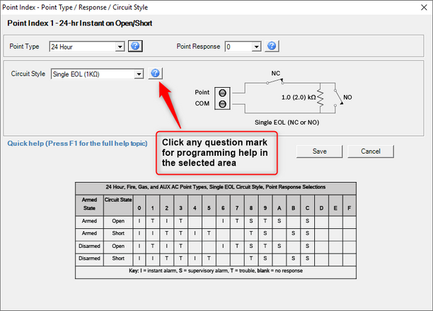
2. Point Type/Response/Circuit Style: This area contains the most important settings of the profile. All three parameters are displayed in a single page to show the interaction between settings. Double-click the point type in the profile to open the configuration page (see figure 2).

3. Point Type: Selects the purpose of the point. Determines whether the point is controlled by arming and disarming (All-On or Part-On) or armed ‘24hours’. The point type also determines whether a Burg, Fire or Gas event is generated. Keyswitch point types are used to modify the arming state of an area. The Aux AC Supervisory type is used to monitor an auxiliary AC power source while following a programed AC Fail Time before reporting a trouble .
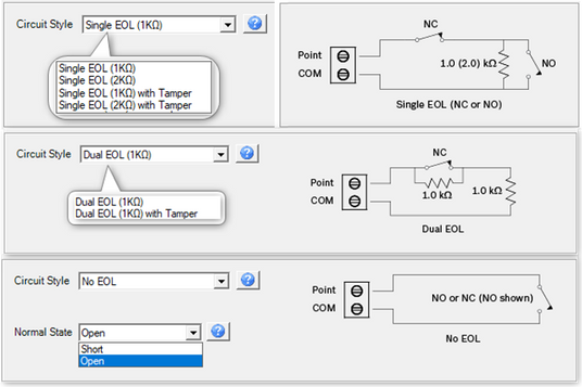
4. Circuit Style: Provides options to configure the panel program to match the end of line supervision wiring at the device. The panel can detect whether a point is Normal/Open/Short with a 1KΩ or 2KΩ EOL; or Normal/Faulted with No EOL. The Dual EOL option provides supervision of a secondary switch, such as a tamper switch, in the protected circuit. Available options are;
- Single with 1KΩ or 2KΩ.
- Single with 1KΩ or 2KΩ EOL with Tamper response.
- Dual with 1KΩ.
- Dual with 1KΩ EOL with Tamper response.
- No EOL with normal state as Open or Short.
5. Circuit Style wiring diagram: A wiring diagram is displayed for a visual representation of the end of line supervision. Its purpose is to assist programmers with selecting a point response when using either a N/O or N/C switch. Three wiring diagrams are possible and the one which displays depends on selections for point type, response and circuit style.

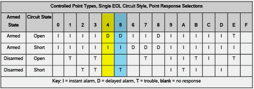
6. Point Response Tables: Provides options for selecting the panel response to the point state becoming open or short. Several tables are possible and the one which displays is determined by selections made for point type and circuit style. Figures 4, 5 and 6 display examples of selecting a point response for various point types .
- Example 1: Point type: Part-On and Circuit Style: Single EOL.
- Use response 4 to start an entry delay (D) in an armed area when the normally closed door contact is opened. An instant alarm (I) is generated if the point state becomes short due to cut wires or a broken switch while the area is armed. No panel response is generated if the point state becomes open or short while the area is disarmed.
- Use response 5 to generate a trouble condition (T) when the area is disarmed and the point becomes short due to damage to wires or door contact (see figure 4)

- Example 2: Point type: Interior and Circuit Style: Single EOL with Tamper.
- Use response 0 for normally open motion detectors that integrate a tamper switch. The panel will generate an instant alarm (I) when motion is detected causing a short point condition while the area is armed. A tamper event is generated when the tamper switch is faulted causing an open point condition.
- Use response 1 to add an entry delay (D) for interior follower motions. Note that several point responses are possible depending the normally open or normally closed alarm and tamper contacts (see figure 5)

- Example 3: Point type: Custom Function with Circuit Style: Single EOL.
- Select a point response to execute the custom function when the point state becomes open or shorted. For example, response 6 will execute the custom function when the point state becomes open whether the area is armed or disarmed. There is no response if the point state becomes short.
- Use Response 9 to add a Trouble (T) if the point state becomes short due to cut wires or a broken switch (see figure 6).

7. Press ‘F1’ to access help: The remaining fields in the profile are explained in detail in help screens, which are available by selecting the field and pressing ‘F1’.
Enable the point in Point Assignments.
1. Assign the Source to be used by the point for interfacing with to the control panel. Double-click Source to view the options available for a selected address. Note that some Source options are only available for use with the addresses indicated below.
- Zonex: Assign to points using a zonex interface (e.g. D8125, D8128D or D8125MUX). Available on B8512G for addresses 9-99. Available on B9512G for addresses 9-126 or 129-247.
- Octo-input: Assign to points using a B208 Octo-input card. Available for addresses 11 and higher which end in 1-8 (e.g. 11-18, 21-28… 101-108, 111-118 and etc.). Octo-input is not available for any point ending in 0 or 9.
- Wireless: Assign to points using a Radion B810 or Inovonics B820 wireless interface. Available for any address 9 or higher.
- Onboard: Only applies to onboard points 1-8 and is not changeable.
- Output: Assigned to points which are connected through logic to an output of the same number. There is no physical device associated with this point. Available for any address 9 or higher.
- Keypad: Assign to points using an SDI2 type keypad with point expansion. Available for points using the keypad’s address multiplied by 10 and with 1 through 4 in the one’s place. For example, if the keypad was addressed as 1, the expanded points would be 011-014. If the keypad were addressed as 21, the expanded points would be 211-214.
- IP Camera: Assign to points using an IP Camera with point expansion. Available for the IP Camera’s address multiplied by 10 and with 1 through 8 in the one’s place. For example points expanded off an IP Camera addressed as 1 would be address 11-18. Points expanded off an IP Camera addressed as 11 would be 111-118.
- Popex: Assign to points connected to a B299 interface. Available for any address 9 or higher.
- Door: Assign to points configured through access programming to a door control module such as a B901. Any address available to the panel can be used however, the point must be assigned to the door in the access area of programming. Door cannot be selected in point assignments.
2. Assign the point profile to the point in point assignments. Note: Only enabled points will display in B8512G/B9512G types. Expand point assignments by clicking on the [+] icon in point assignments. Contract point assignments to only see the programmed addresses by clicking on the [-] icon in point assignments (see figure 7).
Figure 7 Expand or contract the point list in point assignments
Still looking for something?
- Top Results

