- Top Results
- Bosch Building Technologies
- Security and Safety Knowledge
- Security: Video
- How to calibrate a Bosch camera (including Map-based calibration and Geolocation)?
How to calibrate a Bosch camera (including Map-based calibration and Geolocation)?
- Subscribe to RSS Feed
- Bookmark
- Subscribe
- Printer Friendly Page
- Report Inappropriate Content
1.1 What is calibration?
1.2 When do I need calibration?
1.3 Camera specifics
1.4 Configuration
1.5 Autocalibration with IVA Pro Traffic
1.6 Map-based calibration
1.7 Assisted calibration with measuring
1.8 Device web page
2.1 What is Geolocation?
2.2 Applications
2.3 Limitations
2.4 Configuration
2.5 Geolocation in Video Security Client
2.6 Configuration via RCP+
2.7 Verification
2.8 Output: The geolocation of tracked objects
1 Calibration
1.1 What is calibration?
The image sensor in the camera transforms a 3D world into 2D pixel. Calibration means giving the camera the possibility to calculate back from the 2D pixel into 3D real world size and coordinates, by teaching the camera about its field of view and perspective.
One important assumption for that is that all objects are on a single, flat ground plane.
Calibration is determined by the following values:
- Tilt angle: The angle between the horizontal plane and the camera. A tilt angle of 0° means that the camera is mounted parallel to the ground; a tilt angle of 90° means that the camera is mounted top-down in a birds eye view perspective. The flatter the tilt angle is set, the less accurate the geolocation of the tracked objects will be. Estimates are no longer possible when you have reached 0°.
- Roll angle: The angle between the roll axis and the horizontal plane. The setting can deviate from the horizontal by up to 45°.
- Height: The vertical distance from the camera to the ground plane of the captured image.
- Focal length: The focal length is determined by the lens. The shorter the focal length, the wider the field of view. The longer the focal length, the narrower the field of view and the higher the magnification. For Bosch IP cameras with an inbuilt lens this value is determined internally by the camera and does not need to be entered.
1.2 When do I need calibration?
- For long-distance perimeter protection via IVA Pro Perimeter or Intelligent Video Analytics. The long-distance surveillance with simultaneous low false alarm rates is possible by using 3D inference of object size to reject false detections.
- For any 3D tracking mode, which improves performance by including knowledge about real-world size and behaviour.
- For speed estimation.
- For Geolocation (see section 2).
1.3 Camera specifics
Some cameras have sensors to estimate their tilt and roll angles, or to determine the focal length of the lens. This information is included into the calibration where possible, so that often only the height of the camera needs to be determined.
Note that due to the camera type, special handling can be needed for the calibration, which is listed here:
- DINION / FLEXIDOME: Calibration is done once for the camera, independent of any VCA Profiles.
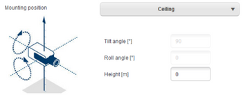
- FLEXIDOME panoramic: The FLEXIDOME panoramic automatically sets the focal length information as the lens is inbuilt. However, it has no internal sensors for measuring angles, and due to the fisheye perspective, sketching of lines will not work either. For most scenarios, the FLEXIDOME camera is either ceiling mounted or a wall mounted, which can be directly selected in the calibration, and thus only the height of the camera above ground needs to be entered manually.
- AUTODOME / MIC: Calibration can be done once for the camera by choosing “standard” mounting position and entering the height of the camera above ground. The assumption is that the AUTODOME / MICs are mounted perfectly straight. Any deviation from that cannot be modeled in the global calibration. For all pan-tilt-zoom positions of the camera, it will then automatically deduce the correct calibration and field of view itself. In case of prepositions with video analytics, the calibration can be fully adjusted to compensate for field of views on different ground planes, non-horizontal ground planes or inaccuracies for large zoom factors via the sketch tool. These calibrations are only active if a preposition is activated, but not when the camera just sweeps across the preposition while on a non-preposition tour or manual steering. In that case, the global calibration – if available – will stay active.
1.4 Configuration
This can be done at
- Device web page: Configuration -> Camera -> Installer Menu -> Positioning
- Configuration Manager: General -> Camera Calibration
- Project Assistant: Calibration
There are different calibration methods available:
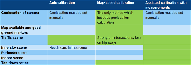
- Autocalibration. Needs IVA Pro Traffic & cars in the scene. Fastest calibration available. See section 1.5.
- Map-based calibration. Needs map and good ground markers (street marking, building edges). Includes geolocation calculation. See section 1.6.
- Assisted calibration with measurements. Slowest method with most effort, but always applicable. See section 1.7.
Choose the calibration method according to this table, with green fields being well-suited:
There is also a very basic calibration available on the device web page, which is described in section 1.8. However, recommendation is to always use Configuration Manager or Project Assistant instead, as calibration there is much more user friendly.
1.5 Autocalibration with IVA Pro Traffic
IVA Pro Traffic offers Autocalibration in combination with selected cameras. These cameras use AI technology to detect and analyse cars in the scene in order to determine calibration parameters. The calibration itself is therefore reduced to a single click, followed by the usual manual verification.
Autocalibration is part of IVA Pro Traffic and available on selected CPP14 cameras. For the full list of supported cameras, please check the IVA release notes.
To start the configuration, open Configuration Manager, select a camera, and go to “General -> Camera Calibration”. If Autocalibration is available on the camera, then an extra menu point will appear on this page. Select Autocalibration and continue.
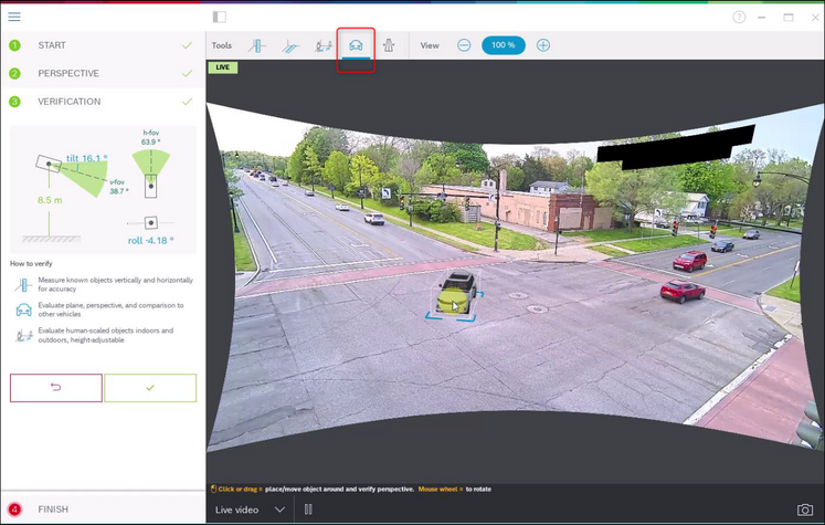
Any camera with Autocalibration continuously analyses the scene for cars, and stores a certain amount of location and size information for them inside the camera itself. It also has inherent knowledge of the camera lens and its characteristics like distortion and focal length. Once Autocalibration is called, all of this information is transferred to the client, here Configuration Manager, and the calibration is inferred from that as soon as enough car samples are collected. There need to be over 25 detections well spread over the image, in case of lack of enough good input a warning will be visible.
Note the curved edges of the video image below, this is the result of automatically correcting the lens distortion to ensure straight lines in the real world are straight in the image as well, in order to get better calibration and verification results.
The 3D bounding boxes in the image show the collected car information. Cars in the foreground appear larger than in the background, which is what the calibration is based on. This visualization also shows in which parts of the image data was gathered. Keep an eye on whether all of the scene you want to monitor is properly represented here, as calibration results outside of where data was gathered may degrade. For example, if no examples in the rear of the image are available, then the calibration there may make wrong assumptions and size, speed and location may not be accurate there. In that case, wait e.g. a day or more until more car samples are available, and then redo the calibration.
While calibration itself is already finished, we always recommend to verify the results. A toolbar with several verification tools is available abovethe video image. You can measure ground distance, height above ground plane, move a virtual person or car around in the scene, or place a virtual road to see whether the narrowing of the virtual road into the distance corresponds with the real world. Below are examples for ground distance and virtual car verification tools. If calibration is not good enough, then either wait for more car detections preferably at different locations in the image and redo the calibration, or use one of the other calibration methods.
Once you are done, “finish” and write the parameters to the camera. This last page shows a summary of the calibration.
1.6 Map-based calibration
The map-based calibration allows fast and easy calibration by marking 4-5 ground points on map and image. Map-based calibration also includes the calculation of the camera’s geolocation. For more information on geolocation, see section 2.
To start the map-based calibration, open Configuration Manager, select a camera, and go to “General -> Camera Calibration”. Alternatively, use Project Assistant, select a camera and go to “Calibration”. Then, select “Map-based”.
Next, you need to select the area where the camera is located from the world map, which can be done via address or exploration.
The next step is distortion handling, which is optional and can be skipped. To calculate distortion, mark lines that are straight in the real world, but curved in the image. Ensure the lines follow the curve in the image. In this example, all lines are straight enough so the step will be skipped. You can find more information on distortion in the chapter on assisted calibration in section 0.
Now we come to the heart of the map-based calibration. See the camera image to the left, and the map to the right. Rotate and zoom the map until it is aligned with the camera image, by using mouse wheel or the buttons to the bottom of the map.
Click on the numbers between the camera image and the map, and drag them into both. These are your markers. Choose corners where possible to place the markers for best accuracy. Ensure that each marker is placed at the same position in camera image and on the map. Ensure to distribute the markers well over your image.
Once enough markers have been placed, the calibration is done automatically and the camera image will be projected onto the map. Use the Overlay slider to make this projection more or less transparent, and see how well it fits onto the map.
Continue with the verification. You can place a person or car in the camera image and map simultaneously to see whether its size and position is correct.
You can also measure ground distances or height above the ground plane, and the results will be displayed simultaneously in the camera image and the map.
If the accuracy is not enough, go back to “Map” and adjust your markers. Otherwise, click on Finish and write the parameters to the camera.
1.7 Assisted calibration with measuring
This calibration uses internal sensors from the camera and user input. Alternatively, user input can be given by measuring heights and distances on the ground, for example, by marking a person walking through the scene. The calibration tool guides users through all necessary steps. It supports calibration from recordings, allowing a person to walk through the scene and be used as a known reference in the calibration process afterwards.
Assisted calibration is available with Configuration Manager 7.70 and Project Assistant 2.3.
Available camera sensors, depending on camera and lens type, are:
- Tilt angle
- Roll angle
- Focal length
Also, for some cameras, the lens distortion is provided automatically.
Available measuring elements are
- Ground distance
- Height above ground (vertical element, drawn from the ground to the corresponding height)
- Person (vertical element, drawn from the ground to the corresponding height)
- 90° angle on the ground
To best prepare this method of calibration, and also the verification, ensure that you have measured at least one distance on the ground looking into the distance, and 2-3 height above ground, for example, by walking through the scene yourself and taking snapshots or a short video of that. Ensure that at least one of the vertical elements is at the furthest position you want to monitor, and that the rest is distributed well over the image, including to the left and right.
For top-down or birds eye view, it helps to have two orthogonal ground distances prepared, as well as two examples of a person walking through the scene, one in the middle of the camera image, and one further to the border. Though note that panoramic cameras are not supported with this calibration, there just measure the height and input it manually.
To start the assisted calibration with measuring, open Configuration Manager, select a camera, and go to “General -> Camera Calibration”. Alternatively, use Project Assistant, select a camera and go to “Calibration”. Then, select “Measure” and continue.
To best guide you through the calibration, three different scenarios are distinguished:
- Steep, top-down or birds eye view. Here, tilt is typically 90°, roll is set to 0°. Often, the focal length is known and can be taken from the camera, thus only the height of the camera above ground needs to be entered.
- Near range until ~50m. Here, the internal camera sensors are good enough in their accuracy and should be taken for the calibration. If the focal length is also known to the camera, then only the height of the camera above ground needs to be entered, or 1-2 measurements from the scene can be used.
- Far range beyond 50m. Here, the accuracy of the internal roll and tilt sensors is often not sufficient, and calibration needs to be done manually via measurements from the scene.
In the case here, the longest distance is 80m, so “far” is correctly selected.
In the screenshot above you can also see that several snapshots were already prepared for the calibration.
The next step is distortion correction. Take a look at the camera image to see whether lines that are straight in the real world are curved in the camera image. If so, then mark these lines, and use the middle node of your line to curve it until it fits to the line in the image. Note that the lines need not be on the ground, and can be vertical or horizontal. It is best to mark lines near the image borders.
In the example here, there is a slight distortion, which does not necessarily need to be corrected, so this step can be skipped.
The next step is to describe the camera perspective. Note that for every value to be calculated, the choice is between
- Calculating the value via measured scene elements drawn into the camera image.
- Measuring and entering the values itself. Often used for camera height above ground
- Using the camera sensors if available. Recommended mostly for near views.
The calibration here starts with marking a ground distance. Note that selecting one going into the distance is preferred, as ground distances from left to right are less stable for the calibration.
Next, the person in the image is marked:
And another two times. You need at least as many drawn elements as calibration parameters to be estimated:
Note that you can zoom into the camera image with the mouse wheel for more accurate drawing:
Once enough different and distributed calibration elements are available, the calibration is calculated, and the results shown to the left in the workflow column. In addition, all calibration elements gain a “shadow”, which is their back projection according to the calculated calibration. The better the shadow fits with the original calibration element, the more accurate the calibration. Note also that the calibration elements here were well distributed in the scene, with examples to the front and rear as well as to the left and right of the target area.
It is always recommended to verify the calibration. For that, you can again mark a ground distance:
Or any vertical elements like persons:
Again, ensure that the object size in the furthest distance fits well, as this will have the most impact on the calibration:
If the calibration is not good enough, then go back to perspective. Otherwise, continue and write the parameters to the camera:
1.8 Device web page
Manual calibration is also available on the device web page. The values can be entered directly, or a sketch functionality can be used to mark ground length, height above ground and angles on the ground similar to the assisted calibration with measurements. However, there is only limited functionality here and it is strongly recommended to go to Configuration Manager or Project Assistant instead, where calibration is much more user friendly.
In the sketch-based calibration, the round arrows show that sensor values from the camera are available. Click on them to take these values into the calibration. For those values which should be determined via the sketched and measured ground length, height above ground or angles, check the “Calculate” checkbox. Otherwise, the values need to be entered manually.
For the PTZ camera, the selection of the preposition on which to apply the calibration is available. Also, a global calibration is available which assumes perfect vertical alignment of the camera, needs the height of the camera above ground, and takes the PTZ motor positions to estimate calibration from there.
- DINION / FLEXIDOME
- FLEXIDOME panoramic
- MIC / AUTODOME
2 Geolocation
2.1 What is Geolocation?
Geolocation is the identification of the real world geographic location of an object. For Bosch IP cameras, geolocation is the position of the Bosch IP camera as well as the objects detected and tracked by IVA Pro, Intelligent Video Analytics, Essential Video Analytics or Intelligent Tracking in this camera either in the global positioning system (GPS) or in a local map coordinate system.
2.2 Applications
|
 |
2.3 Limitations
- Only possible on planar ground planes
- Geolocation of the camera must be set accurately
- Calibration of the camera must be set accurately
- Video analytics tracking mode must be a 3D tracking mode
- Geolocation for Intelligent Tracking only available on CPP7.3 & CPP13
- Accuracy of the position decreases with distance
- Due to lens distortion, the geolocation of objects at the borders of the video will be less accurate
- Geolocation of partly occluded objects may be displaced: If the lower part of the objects is occluded, the foot position on the ground plane cannot be determined accurately.
Support by viewers / video client / video management systems needed. Currently only supported by Bosch Video Security Client 2.1.
Step-by-step guide
2.4 Configuration
This can be done at
- Device web page: Configuration -> Camera -> Installer Menu -> Positioning
- Configuration Manager: General -> Positioning
- Map-based calibration (see section 1.6)
- Video Security Client: Edit camera (see section 2.5)
First, a coordinate system needs to be chosen. There are two options:
- WGS 84, the most used GPS coordinate system. It describes the position of the camera on the earth in the spherical latitude and longitude coordinates. In addition, the ground level above sea level can be set.
- Cartesian, allowing a simple description of local 2D / 3D maps. The Cartesian coordinate system describes the local space with rectangular X, Y and Z coordinates, where X and Y describe the ground plane and Z the height.
For both coordinate systems, the direction into which the camera looks is described by the azimuth angle. The azimuth is defined as zero in the east or along the X-axis and a positive azimuth angle means that the camera is turned counter clockwise when viewed from above, resulting in north at 90° or along the Y-axis, west at 180° and south at 270°.
2.5 Geolocation in Video Security Client
Starting with version 2.1, the Video Security Client offers a map view for geolocated cameras with WGS 84. It provides a map view including the locations of the cameras and the object tracked by Intelligent Video Analytics, Essential Video Analytics or Intelligent Tracking, as well as an easy way to configure the cameras geolocation.
The maps for needed areas of the world will be downloaded and cached for 30 days, allowing offline-display in this time span. If no maps are available, then camera location and tracked objects will be shown on an empty background.
To configure the cameras WGS 84 coordinates via the Video Security Client, edit the corresponding camera, and scroll to the bottom of its settings. There you can set the coordinates either by hand, or change them via their visualization:
For AUTODOME / MIC cameras, the viewing direction shows their home direction, which stays constant even if the PTZ camera is moved around.
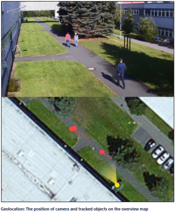
Click on the map in the lower left of the Video Security Client to open it in a larger view. Camera position and viewing direction are displayed on the map in yellow, and all tracked objects in red. The map view is available during live viewing as well as for playback of recordings.
2.6 Configuration via RCP+
Remote Control Protocol plus (RCP+) is a remote control protocol including the ability to send read and write commands to a device, and to subscribe for messages. Using RCP+, the following tags and configurations can be read and set:
- CONF_CAMERA_POSITION: Geolocation of the camera, either none, WGS 84 or Cartesian.
- CONF_CAMERA_ORIENTATION: Azimuth, tilt and roll angles
- CONF_CAMERA_SURROUNDINGS: None or elevation above flat ground plane.
Note that IVA Pro / Intelligent Video Analytics / Essential Video Analytics tracking modes cannot be set directly via RCP+, though a full video analytics configuration can be uploaded.
For further details, please see the RCP+ documentation or contact the Integration Partner Program team (http://ipp.boschsecurity.com).
2.7 Verification
Ensure camera is calibrated, geolocation is set and a 3D tracking mode has been chosen for the video analytics.
Now check whether the object position on the map fits with the objects position in real world to see whether everything is correct.
2.8 Output: The geolocation of tracked objects
All the information about objects detected and tracked by Bosch video analytics is available in the so-called metadata, and transmitted and stored together with the video. It can be accessed via a separate Remote Control Protocol plus (RCP+) stream or via real time streaming protocol (RTSP). Tools for understanding the proprietary metadata stream are available upon request through the Integration Partner Program (http://ipp.boschsecurity.com).
In the metadata, for every object its geolocation is added in the tag object_current_global_position whenever geolocation and calibration of the camera are available. It contains either the longitude, latitude and height above sea level for the WGS 84 coordinates, or X, Y, Z for Cartesian coordinates, depending on which coordinate system was provided as geolocation for the camera itself.
Still looking for something?
- Top Results


