- Top Results
- Bosch Building Technologies
- Security and Safety Knowledge
- Security: Video
- How to configure Microsoft Windows Server as iSCSI target for Bosch video surveillance env...
How to configure Microsoft Windows Server as iSCSI target for Bosch video surveillance environment?
- Subscribe to RSS Feed
- Bookmark
- Subscribe
- Printer Friendly Page
- Report Inappropriate Content
This article describes how to configure a generic Microsoft Windows Server (2012 R2, 2016 or 2019) based server to serve as an iSCSI target for a Bosch video surveillance environment.
SCSI (Small Computer System Interface) is most commonly used for the communication between computers and peripheral devices, such as hard drives.
iSCSI enables devices to use SCSI over a network interface, therefore it makes a lot of sense for cameras to use iSCSI to record video.
The camera is a small computer that needs a (network) connection to a "hard drive" to store video footage. In other systems this job is performed by the network video recorder (NVR).
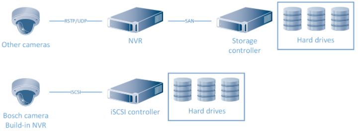
Image: Network Video Recorder versus Bosch iSCSI based storage. The Storage Area Network (SAN) could also be iSCSI based.
A network video recorder introduces a single point of failure: all video streams are being processed by a single software process. When this process fails (hardware failure, software crash) a standby network video recorder can connect to those cameras and take over the recording process. This process consumes some time and will result in a small recording gap. A network video recorder does not exist in a Bosch environment. However, there is one exception: when non-Bosch cameras are used a network video recorder called Video Streaming Gateway is used to record streams from these cameras onto the iSCSI environment.
|
🛈 Microsoft Server Windows 2016 This guide is based on Microsoft Windows Server 2012 R2. Microsoft did not make major changes in the transition to Windows Server 2016 or Windows Server 2019. This guide could therefore also be used as a guide for Windows Server 2016 or Windows Server 2019. |
Step-by-step guide
Microsoft iSCSI Target
The Microsoft iSCSI target is part of all Windows Server editions. It will pick-up the iSCSI traffic coming from the camera and will write it the storage device. This storage device can be connected to a storage area network, but can also reside within the same system as local hard drives.

Since Windows Server 2012 R2 the iSCSI target support up to 544 iSCSI sessions (source: Microsoft Technet - iSCSI Target Server Scalability Limits). For fail-over purposes and, depending on the configuration, a camera connects to an active iSCSI target and a passive iSCSI target simultaneously. Bosch recommends to allocate up to 256 cameras to a single Microsoft iSCSI target based on Windows Server 2012 R2.
Configuration
|
🛈 Windows Advanced Firewall Before starting the configuration, the Windows Advanced Firewall needs to allows iSCSI traffic to pass. Microsoft Technet - Configuring Windows Firewall for iSCSI Software Target describes how to achieve this. |
- Install the iSCSI target
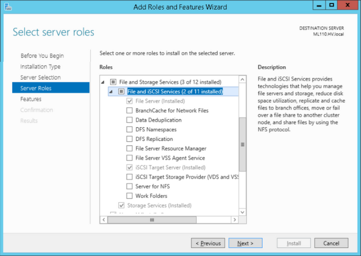
Check if the Role "File and Storage Service iSCSI Target Server" is installed. Start the "Server Manager". This will start the "Add Roles and Features Wizard". Click "Next".
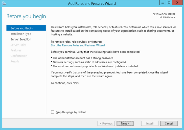
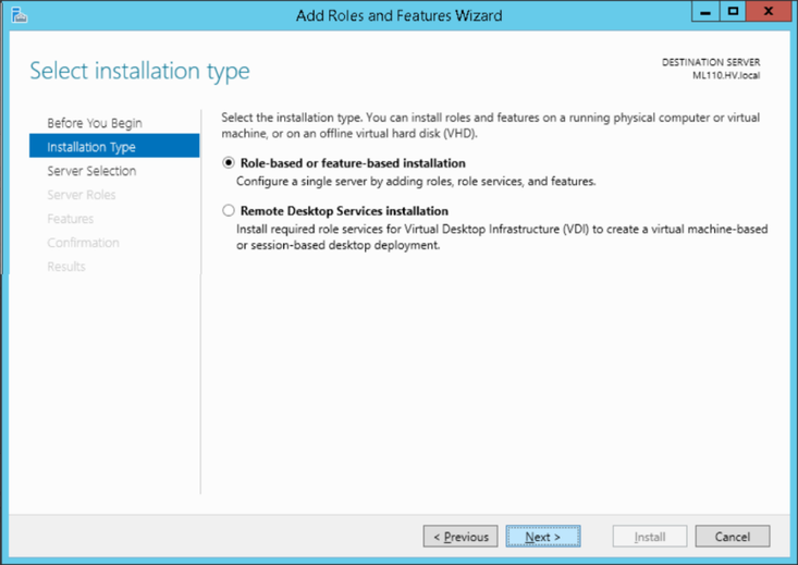
Choose the "Role-based or feature-based installation" option.
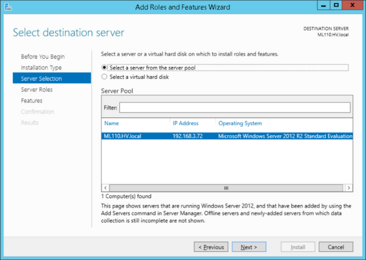
Select the system on which the iSCSI target needs to be installed (normally this would be the local system on which the wizard is started).
Check of iSCSI target Server is installed. If not installed, select iSCSI Target server and install the role.
- Configure the iSCSI target
|
🛈 Configure storage device Before continuing with this guide, the (optional) storage arrays need to be configured and connected to the Windows operating system. This means the arrays should have a drive letter assigned to them. As this process is different for each and every storage vendor, Bosch recommends to contact the storage vendor for documentation regarding this process. |
The iSCSI target server uses virtual disks, which are assigned to an iSCSI target. The virtual disks are used for recordings of cameras. The size of the virtual hard disks represent the size of LUN’s assigned to the VRM.
Bosch recommends to use a maximum LUN size of 2 Terabyte. A single Video Recording Manager can handle up to 2 Petabyte.
If more storage is required, another Video Recording Manager needs to be added.
To start the configuration, open the Windows 2012 Server Manager, select "File and Storage Services" and click "iSCSI".

Start the wizard: “To create an iSCSI virtual disk, start the New iSCSI Virtual Disk Wizard”. Select the volume to create new virtual hard disks.
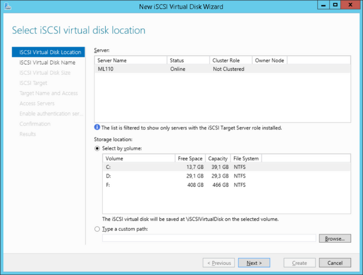
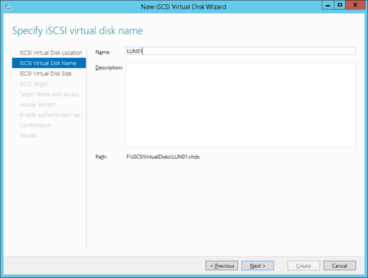
On this server the F drive is used to create the virtual disks. In the next step, the disk name needs to be specified.
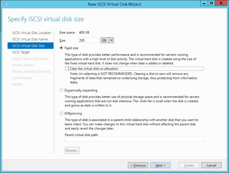
Define the size of the virtual hard disk, minimum 200 GB and maximum 2048 GB and make sure “clear the virtual hard disk on allocation” is checked. Multiple disks need to be created if the storage capacity of the system exceeds 2048 GB.
One iSCSI target can contain multiple disks. Each disk will be represented as a LUN.
When a new system is created: create a new iSCSI target and define the name of the target. When a new virtual disk is added to an existing system: select the iSCSI target to which the disk needs to be added.
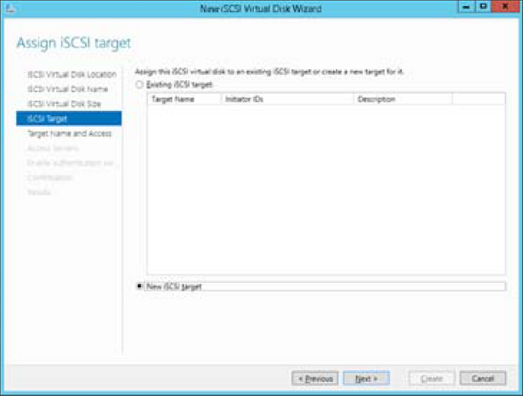
In the "Target name and Access" window the access to the target is specified. We recommend you to configure an IQN or IP based filter that ensures only the whitelisted devices have access to the iSCSI target. For demonstration purposes the "*" can be used in the IQN filter to whitelist all devices.

CHAP authentication is supported and can be enabled as required. The Video Recording Manager and cameras (described in their respective manuals) need to have a matching configuration.

Finish the wizard.
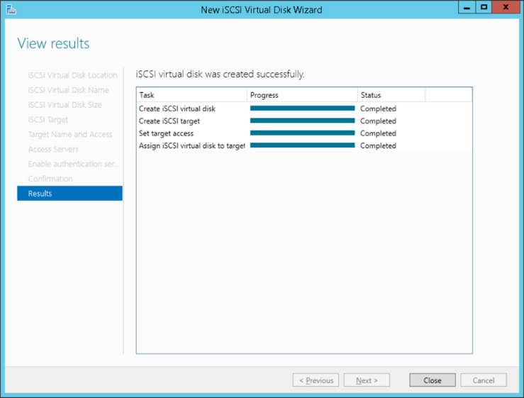
- Configuration using Powershell
|
#create target New-IscsiServerTarget TG0 -InitiatorID Iqn:* $disk = Get-WmiObject Win32_LogicalDisk -Filter "DeviceID='D:'" | Select-Object Size,FreeSpace #calculate how many vhdx files to create and then do it in a loop Write-Host "total space on volume in bytes " $disk.Size Write-Host "free space on volume in bytes " $disk.FreeSpace $freeSpaceInMB = [int]($disk.FreeSpace / (1024*1024)) Write-Host "free in MB " $freeSpaceInMB $lunSizeInMB = 1950 * 1024 $lunCount = [int]($freeSpaceInMB / $lunSizeInMB) For($i=0; $i -lt $lunCount; $i++) { $currentFileName = ("d:\" + "vhd_" + $i + ".vhdx") New-IscsiVirtualDisk -DevicePath $currentFileName -Size 1950GB -fixed -DoNotClearData Add-IscsiVirtualDiskTargetMapping -TargetName TG0 -DevicePath $currentFileName } |
- BVMS configuration
When adding a new storage device to the BVMS (as described in the BVMS configuration manual) some parameters are required.
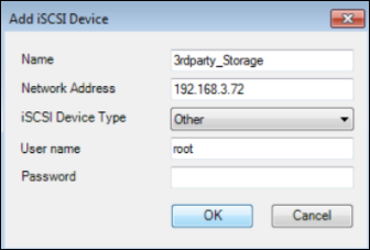
Specify the values as required, and use a Windows user-name and password which has administrative access on the iSCSI server.
Activate the configuration before making further changes.

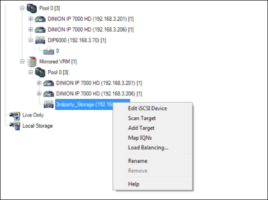
The target needs to be scanned once the target configuration is activated.
|
🛈 WARNING When the BVMS Config Client is not able to scan the iSCSI target, it is most likely the selected user account does not have the rights to provide the BVMS with the correct information. Ensure that the Windows user is part of the "administrators" group. A description on how to do this can be found on Microsoft Technet - Add a member to a local group. |
After adding the iSCSI device an error message could pop up. This message indicates the current file format on the LUN is not recognized and it needs to be formatted. Click "OK".

Select the LUN(s), and click "Format LUN".
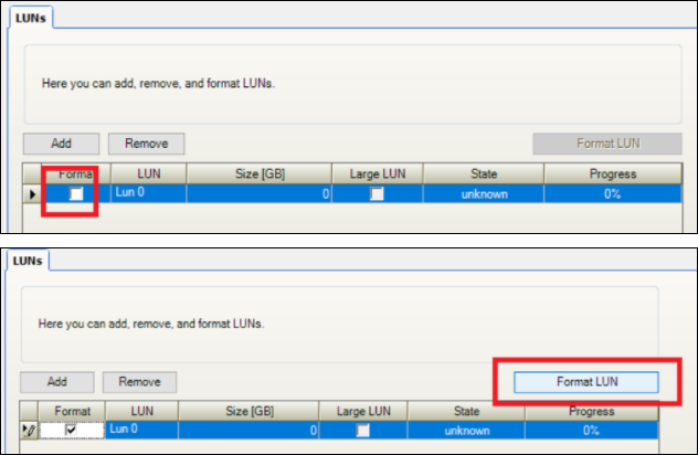
As this will be a new system no data is currently stored on the LUNs, the warning message can be accepted.

Right click on the iSCSI device, and click "Load balancing". Set the upper limits for the permitted bit rate and the number of simultaneous iSCSI connections for each iSCSI system. If these limits are exceeded, data is no longer being written to the iSCSI system and is lost.
|
🛈 Performance The load balancing limits are very important: If the storage device cannot offer the performance which is configured, recording gaps might appear and cameras might loose connections to the storage device. |
- Storage system
As storage systems from different vendors differ in configuration, the specific configuration details are not in the scope of this article. Some general recommendations regarding the configuration of a storage system are given.
- Cache
There are three main caching techniques that can be deployed:
- Write-through cache: directs write I/O onto cache and through to underlying permanent storage before confirming I/ O completion to the host.
- Write-around cache: write I/O is written directly to permanent storage, bypassing the cache.
- Write-back cache: write I/O is directed to cache and completion is immediately confirmed to the host: this is the recommended way of writing for video footage.
Troubleshooting
Recording gaps and camera disconnect messages can appear if the storage system experiences problems, or is overloaded.
1 Video Recording Manager
The Bosch Video Recording Manager included a lot of tools to evaluate the performance of the system and analyze problems. The Video Recording Manager dashboard can be opened by browsing to the IP address on which the Video Recording Manager is installed. Alternatively the Video Recording Manager dashboard can be opened by right-clicking on the Video Recording Manager in the BVMS Config client, and clicking "VRM monitor".
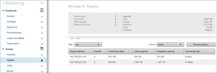
The Targets page (under Storage), shows the individual targets and their status.
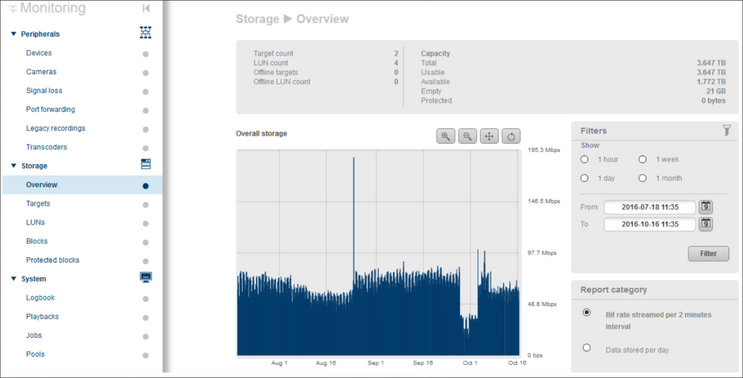
The Storage Overview page shows the total consumes bandwidth and system capacity.
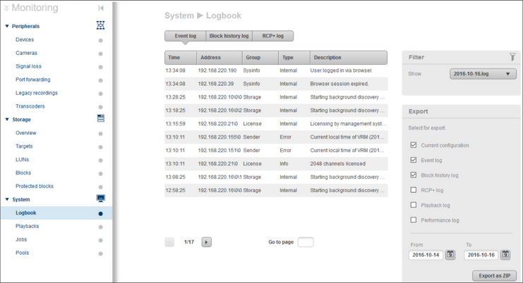
The System Logbook shows current system events. If cameras are disconnected from specific target, messages will show up in the logbook.
2 Windows Resource Monitor
The Windows operating system also has a lot of tools on-board which can help analyze performance issues. The Resource Manager can be used to look at read/write rates, active time and response time.
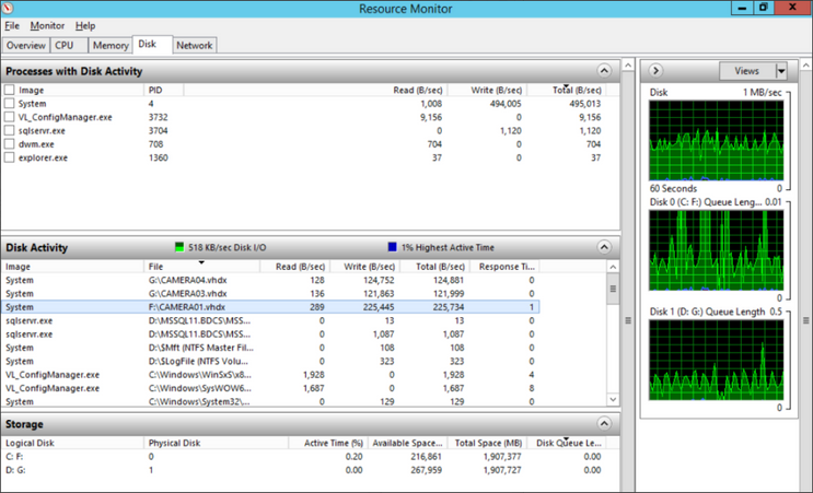
Microsoft Technet - Using performance monitor describes how to use the performance- and resource monitor.
3 Hardware specific tools
Storage vendors may have hardware specific tools to monitor the status of the storage devices. These can give additional insights into the status of a device.
Most of these tools also allow system monitoring, and can alert when (for example) a hard-drive fails. The BVMS supports receiving SMTP messages from these devices, and can present these to the operator for follow-up. The configuration of SMTP is outside of the scope of this article, but can be found in the BVMS configuration manual.
After-sales support
When using Bosch storage devices, an end-to-end Bosch engineered system is delivered. As a result, components are well known and expertise is available to analyze and solve the most difficult issues.
Using non-Bosch storage devices is therefore a challenge: it is not possible to have in-depth knowledge on all storage brand and devices. This section will give clear insights in what Bosch technical support can and cannot do.
|
🛈 WARNING Storage devices are complex and require specific knowledge. Ensure the engineers who are designing and configuring the storage system are properly trained by the storage manufacturer and are able to troubleshoot together with Bosch technical support whenever problems arise. Knowledge on how to operate Wireshark, Windows Server and basic networking is required. |
Whenever problems arise, Bosch technical support will help with:
- Verifying the camera can reach the iSCSI target, based on the configuration guide in this article.
- Verify the video footage arrives on the network interface of the iSCSI target (using Wireshark).
- Analyze camera logfiles.
- Analyze VRM logfiles.
Bosch technical support will help to ensure that the data coming from the camera arrives at the storage server.
Bosch technical support will not help with:
- Performance analysis of the storage.
- Hardware configuration of the storage (includes configuration of LUN's).

External information
The use of non-Bosch storage devices is based on the usage of IT standard equipment. The information linked below can be used as a reference for further information. For specific configuration manuals the storage vendor should be contacted.
- Configuration guide for the Microsoft iSCSI target on Microsoft Technet (can be used to configure the Microsoft iSCSI target, which is part of all Microsoft Windows Server editions)
- Explanation of the iSCSI protocol on Wikipedia (readable description of the iSCSI protocol)
- Recommended RAID settings for DIVAR IP 6000 (these can also be applied for other storage systems)
- DIVAR IP & RAID articles
Still looking for something?
- Top Results
