- Top Results
- Bosch Building Technologies
- Security and Safety Knowledge
- Security: Video
- How to set up a Video Verification service (triggered by intrusion panel) in Bosch Alarm M...
How to set up a Video Verification service (triggered by intrusion panel) in Bosch Alarm Management?
- Subscribe to RSS Feed
- Bookmark
- Subscribe
- Printer Friendly Page
- Report Inappropriate Content
Video Verification Service

To prevent vandalism & theft outside opening hours.
Plug-and-play camera connectivity provides video evidence to allow operator to choose appropriate escalation path for intrusion panel alarms.
Please follow below steps to set up a Video Verification service.
Step-by-step guide:
1. Prepare camera and intrusion panel as Installer or Integrator:
1.1 Add the camera to the Alarm Management
Please follow the related article to add a camera to Alarm Management:
a. Add Remote Portal cameras to Bosch Alarm Management
b. Add a camera with its MAC address
If the intrusion panel triggers the Video Verification over input contact:
- Additionally connect the camera’s input contact to the panel’s relay.

1.2 Configure the Bosch B-/G-Series Panel
1.2.1 B-/G-Series configuration: IP Cameras
1. Launch the Remote Programming Software (RPS) and open the desired panel account.
Navigate to Panel Wide Parameters and select IP Cameras.

2. Select Camera 1 and enter a name for the camera. The name entered here does not affect camera names in the IP camera.

3. Enter the URL or IP Address of the IP camera the panel will connect to.

4. Leave the RCP+ port set to the default parameter. The RCP+ port is pre-set to 1756 in all Bosch IP cameras.

5. Enter the camera’s service password.

6. A supervision period of 10-128 seconds can be entered if you want to monitor the IP camera’s connection to the control panel. This sets the amount of time the panel will wait before reporting the IP camera as missing.

7. If assigning a single IP camera to the panel, the Live (Video) Port # can be left at the default value of 80. If assigning multiple IP cameras to the panel, unique camera port numbers are required. A port range of 10,000-10,100 can be utilized.

Note: To adjust the remote port of the camera to match the settings described in step 7, use a web browser and navigate to the IP address of the camera.
Navigate to: Configuration > Network > Network Access > HTTP browser port
8. The HTTPS option is not used by this application and can be left at the default value of No. If secure network communication between the camera and the Remote Security Control (RSC) app is desired, set this option to Yes.

9. Enter the camera’s Live password.

1.2.2 B-/G-Series configuration: Point Assignments
1. In RPS, select Points and then Point Assignments.

2. Click on the
icon to expand the available points within point assignments. For point 11, set the Point Source to IP Camera and then select OK.
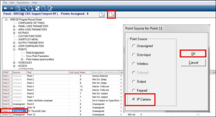
3. Select Point Text to enter the desired name for the camera.
Note: The name entered here does not affect the camera’s name set in the IP camera.
Set the Index to 0, set the Area to 1, set the Output to 11.

Note: This chart explains how B Series panel outputs are associated to the camera’s virtual alarm inputs.

1.2.3 B-/G-Series configuration: Output Parameters
Area Wide Outputs
1. Navigate to Output Parameters and select Area Wide Outputs

2. For the Alarm Bell output, program an 11.

Output Configuration
1. Navigate to Output Parameters and select Output Configuration.


3. Select Output Text and enter a desired name.

4. Save and send the updated RPS data to the panel.
1.3 Verify the Trigger from the B-/G-Series panel in the Camera
An alarm generated by any non-fire point from Area 1 of the Bosch panel will trigger the camera. The alarm event will be sent to your monitoring center’s cloud instance. It can be viewed by launching the Alarm Management Event list website (/eventmonitor).
Note: For the sake of off-site testing, this is a simulated alarm event. This is done by tripping the alarm output via the Diagnostics section of RPS, and not a “true” control panel alarm. If applicable, an onsite technician can create an actual alarm from any non-fire point in Area 1 and produce the same results.
To verify the trigger from the panel in the camera, perform the following steps:
(Note: These verification steps are only available for cameras, which were added with its MAC address.)
1. Open Cloud-based Services Camera Quick Install website (/install), log in as Technician.
2. Type the MAC address and click 'Add to Cloud'.
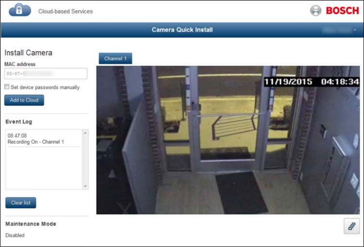
3. Click "Clear list" to clear the Event Log.
4. Trigger the alarm on the Intrusion Panel:
a. While connected to the Bosch control panel via RPS, click on the diagnostics icon within the RPS panel programing page.

b. Select Output and navigate to Output 11.
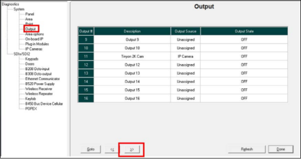
c. Click OFF in the “Output State” column for Output 11. Set the output state to ON and click OK.

d. Click the “Send Changes” button.

5. Verify the trigger in the camera's Event Log
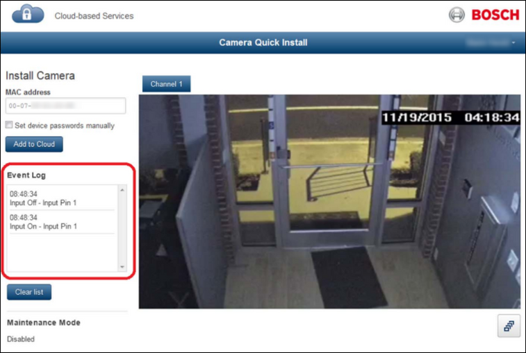
2. Configure the Video Verification Service as Integrator or Config Agent:
To configure the Video Verification service perform the following steps:
2.1 Add the camera to a Site
1. Open Cloud-based Services Configuration website (/config), log on as Integrator or Config Agent.
2. Enter the related Account - or create a new Account for the customer.
3. Enter the related Site - or create new Site.
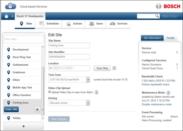
4. Enable 'Video Clip Upload' if required. (If video clip upload is disabled, an alarm snapshot is stored).

5. Click '+' button to add the camera to this Site.
6. Please follow the related article to add a camera to Alarm Management:
a. Add Remote Portal cameras to Bosch Alarm Management
b. Add a camera with its MAC address
7. Rename the device (camera) and click 'Save Changes'.
8. Select the required trouble and tamper warnings, which should be sent to the Monitoring Center and click 'Save Changes'.

9. Click tab 'Channels' and set a Reference Image.
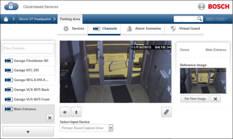
10. Rename the channel.
11. Click 'Save Changes'.
2.2 Configure the Service Scenario
1. Open Cloud-based Services Configuration website (/config), log in as Integrator or Config Agent.
2. Enter the related Account.
3. Click tab 'Services'.
4. Click '+' button to add a Service.
5. Select Service Type 'Video Verification' and give the Service a descriptive name (mission).
6. Select the Site
7. Select the device (camera) and then select the device's input, which is triggered by the Intrusion Panel:
a. use 'Virtual Alarm' if the camera is triggered over IP,
b. use 'Input' if the camera triggered by the panel's output (relay).

8. Select the Alarm Channel
Notes:
- The Alarm Channel is used as the default video input channel for the alarm agent and uploads the alarm video clip (if available and configured for the camera and the service).
- If the trigger already implies an alarm channel, the alarm channel is fixed and cannot be changed. In all other cases the alarm channel can configured to any channel of this site.
9. Optional add further triggers. The Service Scenario is triggered if any of the configured triggering events becomes activated.
10. Optional increase the Trigger Debounce Time (= minimum time between 2 alarms) if you want to get less alarms from this service.

11. Optional enter a Service Identifier.

This identifier can be used in the alarm management to link the service scenario to an intrusion alarm from the same area.
12. Check "Enable event batching" to get all events in one batch.

13. Optional add Automatic Actions, which are executed automatically when the event is processed.

14. Click 'Create'.
2.3 Configure the Site's Map
1. Open Cloud-based Services Configuration website (/config), log in as Integrator or Config Agent.
2. Enter the related Account.
3. Enter the related Site.
4. Click tab 'Map'
5. Drag and draw all cameras of this site into the map and turn the camera icons' arrow in the correct direction.
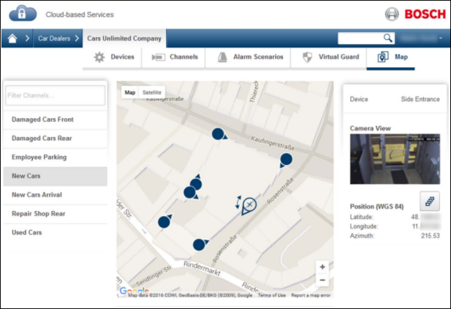
6. Click 'Save Changes'.
3. Verify the Video Verification Alarm as Alarm Agent
To verify the Video Verification service perform the following steps:
1. Open Alarm Management Event list website (/eventmonitor), log in as Alarm Agent.
2. Ask the installer or customer to trigger the alarm on the Intrusion Panel (see above).
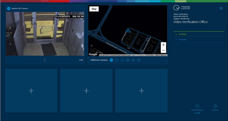
3. Click the new line appearing in the event list, the Operator Interface opens.

4. Verify the alarm:
a. Verification Mode:
i. Alarm image and video clip
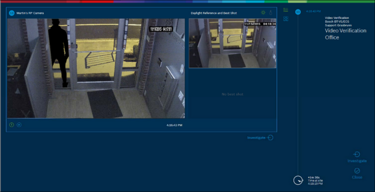
b. Investigation Mode:
i. Live video
Note that a Video Verification Alarm is forwarded to the Monitoring Center independent on the Alarm Schedule and Arming State of a Site.
Video Verification Alarm is just blocked when the Maintenance Mode is enabled for a Site, or when this service is snoozed.
See also the article Troubleshooting Alarm Notification in Operator Interface if no alarm appears in the event list.
Still looking for something?
- Top Results