- Top Results
- Bosch Building Technologies
- Security and Safety Knowledge
- Security: Video
- Who rated this article
Who rated this article
What is ANR 2.0 and what are its functionalities in typical storage failure situations?
Question
What is ANR 2.0 and what are its functionalities in typical storage failure situations?
Answer
Automatic Network Replenishment (ANR) has been an essential feature for Bosch Security Systems storage solutions since more than a decade. It helps avoiding recording gaps even in the case of interrupts in communication between the video source, typically a camera or encoder, and the storage device.
In earlier days, the task of monitoring a gapless recording and in case initiating replenishment was performed by the external “recorder”, then Network Video Recorder (NVR).
Since iSCSI recording was introduced to the cameras and encoders things changed as the recorder has moved into the video source device, making it a logical consecution to also have the camera or encoder taking care for gapless recordings.
Firmware version 5.90 for platforms CPP-ENC and CPP4 introduces the second generation of Automatic Network Replenishment. ANR 2.0 makes use of the video source’s local and dual recording capabilities, thus only becomes available with products supporting both.
Firmware 5.92 improves the initial functionality of ANR to become more robust against local storage media failures and includes a few fixes that allow creating alarm task scripts to demonstrate ANR.
This article describes the mechanism of ANR 2.0 and how it can be set up. In the following ‘camera’ is used as a representative for all video source devices supporting ANR 2.0.
As ANR is still used as a system feature in a wider context, e.g. supported by Bosch VMS 5.0, it is at the moment not directly configurable via the normal Web interface or the Configuration Manager application, thus requires a few RCP commands to be given via scripting to get it functioning without a management system.
1. Camera setup in principle
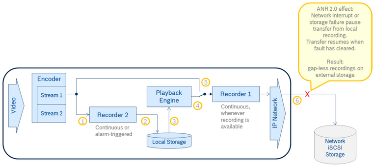
Assuming the camera has an appropriate local storage medium installed, typically an SD card or μSD card, it uses the secondary recording, performed by Recorder 2, to record the video onto the local storage.
The primary recording, performed by Recorder 1, is still used to record onto an external storage medium, e.g. an iSCSI LUN, with the difference of not taking the video encoder output directly but the feed from an internal playback out of the secondary recording.
With ANR mode there is a small delay between the local recording and the playback towards the external recording to avoid transfer underrun. The external recording starts approximately 100 seconds after the local recording was initiated and delay then is managed to stay between 60 and 120 seconds. This must be considered when checking the correct function.
• Recorder 2 takes same input (1) as Recorder 1 would have taken (5) and records onto local storage (2), continuously or alarm-triggered
• Local storage feeds internal playback engine (3) which feeds Recorder 1 (4)
• Delay between local and external recording is between 60 and 120 seconds
• Continuous recordings or alarm snippets are transferred to network storage (6)
2. RCP command extensions and new backup recording status
In RCP commands CONF_HD_RECORD_PROFILES and CONF_HD_RECORD_PROFILES_V2 the encoder index can now be set to value 255 which links the recording with a playback as a source.
The RCP command CONF_ACCOUNT_SETTINGS has been extended by a new account type 4 "recording". This type must be used for ANR, internally building a bridge between the local storage and the external recording. Other account parameters than the type are not relevant for this use.
With the new recording features there is also a new backup recording status introduced which can be checked via RCP command CONF_BACKUP_RECORDING_STATUS and which will be sent as RCP event message when certain load levels of the internal storage are exceeded. The status provides information on whether and how a backup recording is set up. It also gives the internal storage utilization in MByte which allows calculation of e.g. the utilization percentage, helping overall system analysis.
There are two threshold levels for sending the message which are configured with the new RCP command CONF_BACKUP_RECORDING_STATUS_MSG_THRESHOLD. If the storage utilization exceeds the "warning" level (default value: 90%) a message will be sent and the "warning" state is set if not active yet. If the storage utilization falls below the "all clear" level (default value: 50%) while the "warning" level is active, a message is sent again and status returns to "all clear".
3. Camera configuration
The configuration of a camera can be started using the standard GUI elements via Web browser or Configuration Manager, preparing the camera for dual recording with the primary recording targeting external iSCSI storage and the secondary recording targeting the local storage, in our example an SD card.
By default the video source uses encoder profile 3 as being used for recording of Stream 1. The secondary recording must also use Stream 1 as the source for recording. Both storages must be added to the system and prepared accordingly. The two recording profiles must be set to continuous recording.
The specific commands for activating ANR are then added using Alarm Task Scripting and the Web browser pages:
1. Set one of the accounts to type "recording" using the RCP command CONF_ACCOUNT_SETTINGS. The type must be defined as 4 “recording”. All other parameters can be ignored and must not be set but written as zeroes with this command.
2. Modify the secondary recording profile - in our example we use the first profile for both recordings - to continuously back up towards the account that has been prepared for ANR use. To do so, select the respective account on the Recording Profiles page and click “Set”.
3. Configure the primary recording profile to receive its data from this account instead of an encoder output, using the RCP command CONF_HD_RECORD_PROFILES_V2. The encoder number must be set to 255. Since FW 5.92, the RCP command has been enhanced to allow only the necessary successive profiles to be written, each a block of 56 bytes, or 112 digits in the RCP command payload.
With these three steps the camera is prepared for ANR. The last thing is just to start recording.
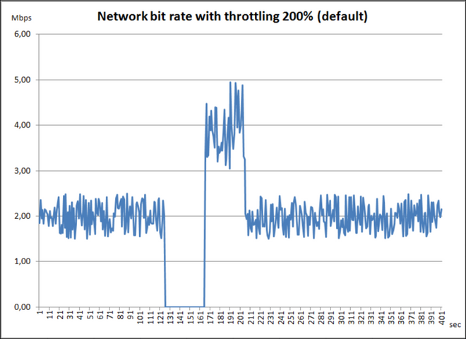
When the camera is then added to a VRM system, ANR can be tested by disconnecting the network interface between camera and iSCSI storage. The recording bar in the timeline of a viewing client will stop. After re-connecting the network, ANR will kick in and transfer the locally buffered recording to the iSCSI storage at the defined replenishment speed, visible in a faster growing recording bar and also in a network traffic monitoring tool, if opened. Once the buffered recording has been transferred, the recording bit rate will go down to normal level.
Default throttling 200%, double bit rate, replenish time same as gap
4. Controlling network bit rate consumption and transfer speed
With ANR mode there is a delay between the local recording and the playback towards the external recording to avoid transfer underrun. The external recording starts approximately 100 seconds after the local recording was initiated and delay then is managed to stay between 60 and 120 seconds.
The new recording mode may create temporary bursts on the network which might cause issues depending on the infrastructure. This can be avoided by limiting the data rates through iSCSI Write Throttle and the transfer (backup) speed from secondary to primary recording.
The new RCP command CONF_ALARM_BACKUP_REC_SPEED_LIMIT affects the transfer data rate per line and is given as percentage of the original recording data rate as well as a maximum data rate in kbps whichever limit cuts first. Backup speed limit of 100% equals a transfer with normal speed. The transfer can be stopped completely by sending a speed limit of 0% and continued again by sending a non-zero speed percentage later. It cannot be stopped by the data rate with a value of 0 as this means to disable the limit for the data rate. The data rate parameter isn't applied immediately but when the next backup starts.
With iSCSI Write Throttle the iSCSI write data rate range is defined for the overall data rate of a device which must be considered for a multi-channel device. The iSCSI Write Throttle has an upper and a lower limit, defined by commands CONF_ISCSI_DATARATE and CONF_ISCSI_LOWERDATARATE. Within this range the limit is typically set to twice the data rate sum of all recorders writing towards iSCSI. For ANR this does make less sense as incoming data is not from an encoder but from internal storage. It makes more sense to set the throttle to a fix value which is achieved by setting lower and upper data rate limit to an equal level.
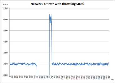
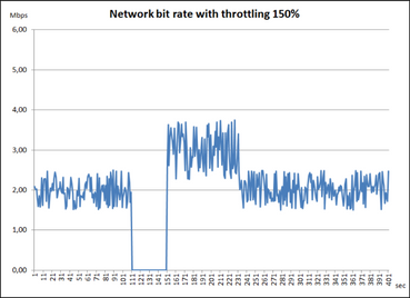
Generally, you have to ensure not to set data rate limits continuously below the data rate of the video encoder to avoid fill-up of the local storage and overwriting of recordings. There should always be sufficient space calculated between bit rate and bandwidth to allow depleting before fill-up. The smaller the throttling percentage the longer depletion takes and the more free storage space is necessary to avoid overwrite due to fill-up.
Throttling 500%, replenish time fifth of gap Throttling 150%, replenish time double of gap
5. Handling of local storage failures
The following scenarios illustrate the functionality of ANR 2.0 in typical storage failure situations. As there is no defined dying-off of local storage, we used a kind of black-and-white scenarios.
ANR 2.0 devices create error messages and events that allow for servicing the devices to restore broken supporting components.
Case 1 describes the typical case ANR 2.0 has been designed for, a network interrupt or external storage failure.
Cases 2-4 describe failures of ANR-supporting components and the resulting behavior.
Case 1: Network interrupt or storage failure
• External storage is not reachable X
• Recorder 1 suspends playback (4) from local secondary recording (3) and local storage buffer fills
• When network connection re-establishes and/or storage becomes available again, playback (4) is resumed as well as recording onto external storage
• Replenishment with increased speed to reduce local storage buffer fill level
Case 2: Local storage failure – write error (partial dysfunction)
• Local storage cannot be filled anymore (2) X but still read (3)
• Recorder 1 takes playback (4) from local secondary recording (3) till end of recording, then switches to Stream 1 directly and continues recording without ANR function (5)
• ANR will be resumed as soon as local storage is replaced
Note: Video from occurrence of failure until completed transfer of local recording will be lost!
Case 3: Local storage failure – write/read error (fatal dysfunction)
• Local storage cannot be filled nor read (2) (3) X
• Recorder 1 immediately switches to Stream 1 directly (5) and continues recording without ANR function
• ANR will be resumed as soon as local storage is replaced
Note: Video footage residing on the local storage will be lost due to storage defect!
Case 4: Internal storage failure with external back-up
• Local storage cannot be filled (2) X
• Recorder 2 immediately switches to external local iSCSI storage and continues recording (7) without a gap
• All ANR 2.0 functionality remains, no recording will be lost
• Due to higher priority of internal local storage – which must be configured in this case - Recorder 2 will switch back as soon as the local storage medium is replaced while Recorder 1 gets playback from external local iSCSI storage (8) until buffered recording has been transferred, then switches back to local storage (3)
In this case, which prevents footage loss due to internal local storage medium failures, ANR is somewhat weakened as it requires the device’s network interface. It is advised to keep the external local iSCSI storage as close as possible to the device. ANR protection is then only given for network failures outside of the local network.
Also, please consider the reduction of overall performance due to the recording data written to the external local iSCSI storage passing the IP network path three times.
6. Load considerations and limitations
ANR 2.0 was tested with a CPP4-based IP camera, DINION IP 7000 HD, to evaluate the maximum video data rate. When the camera was not loaded with an additional playback session, 3.5 Mbps were reached continuously. This is the average bit rate received through playback from local recording while the peak bit rate of Stream 1 can of course be much higher, making use of the many intelligent imaging features for optimal image quality at lowest possible bit rate.
With a local playback session from a client, which is directly playing back from the internal local storage in parallel to ANR, the data rate for external recording dropped to 2 Mbps. The limitation is imposed by processor load causing fill-up of the local storage which can be determined by the RCP command respectively the message CONF_BACKUP_RECORDING_STATUS (see chapter 2). The SD card performance is typically negligible as the computational performance is drawn by dual recording and the playback in parallel.
The local recording to the internal medium stays on its normal bit rate due to recording having higher priority than playback, increasing the fill level of the recording buffer. The drop from 3.5 to 2 Mbps also causes a replenishment cycle after the local playback session is ended. Local playback sessions, especially those of extended continuity, should be avoided, or at least treated with care, to have ANR 2.0 perform as configured.
If external local storage is used (see Case 4), the performance also drops due to the recording data passing the IP network path three times.
Data rates might exceed the measured average for short periods but should also fall below for longer to allow depletion of the local storage fill-up. Continuous overload causes overwriting of recordings that have not been transferred to the external storage yet.
Overload situations might be created by:
• too high quality settings causing constantly too high bit rate,
• more motion than expected on average, creating too high overall bit rate,
• any other settings that put the average bit rate close to or above the available bandwidth,
• local playback sessions,
• or any other condition that puts load on the camera to keep it from reaching the necessary recording bit rate.
To avoid the first three situations it might be considered to use the recording averaging feature on the secondary recording which keeps the utilization of the local storage at an optimum without exceeding maximum bit rate values.
Other cameras might show different performance and limits, also depending on other tasks loading the processor.
Due to its nature, ANR is not applicable to devices without local storage.
Also, it is only applicable with restrictions to a device powered via PoE as it cannot be protected from a failure on the camera’s direct physical network connection.
If ANR does not switch over to network attached storage, this could be due to Time Sync differences between the VRM and the camera.
- ANR is very sensitive to time differences when first setting it up.
- To solve this try rebooting the camera.
7. References
Alarm Task Scripting Language (ATSL)
Documentation can be found on the IP product pages in the Bosch Security Systems online product catalogue or you can find a selection of them here.
RCP+ Documentation
This is included in the respective platform firmware file, available through the IP product pages in the Bosch Security Systems online product catalogue.
Still looking for something?
- Top Results


