- Top Results
- Bosch Building Technologies
- Security and Safety Knowledge
- Security: Video
- Who rated this article
Who rated this article
What are the best practices for surge and lightning suppression (Bosch IP Cameras)?
Question
What are the best practices for surge and lightning suppression?
Related Products
These practices apply to all Bosch IP cameras installed outdoors.
Answer
IP Cameras Surge and Lightning Suppression (Best Practices)
Cameras installed outdoors are typically exposed to surges, transients, and lightning. The wiring and installation details in this guide are based on common practices used at sites to ensure proper surge and lightning suppression.
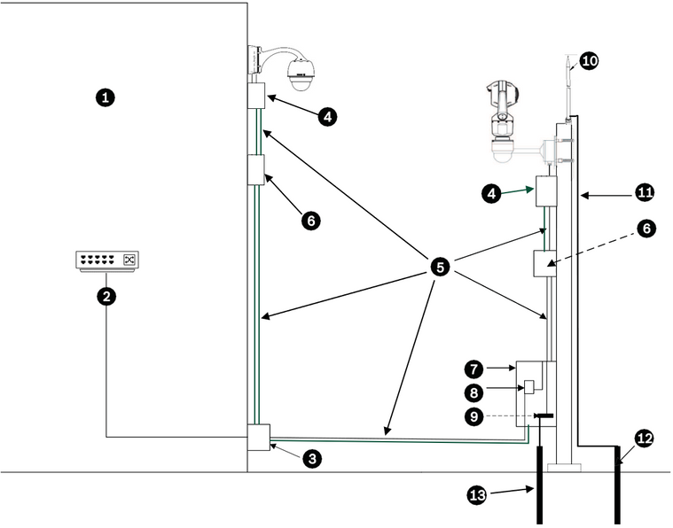
This drawing is an example of the best practices to follow during design and installation. This information is applicable to any IP camera, but the mounting hardware will vary between models.

|
1 |
Indoor main building. |
2 |
Network switch with shielded ports and grounding as recommended by the manufacturer. All network cables must be terminated with shielded RJ45 connectors. |
|
3 |
Surge suppression for indoor equipment at cable entry. |
4 |
Outdoor rated surge suppressor with shielded RJ45 connections that must be mounted as close to the camera as possible. Connect the ground per the manufacture’s installation manual. |
|
5 |
Install Cat5e/Cat6 shielded Ethernet cable such as F/UTP shielded cable with twisted pairs (often referred to as FTP) or S/UTP braided shield with twisted pairs (often referred to as STP) with shielded RJ45 connectors. The cable must be routed through a permanently earthed metal conduit. Earth grounded across the entire span. The cables must be a maximum length of 100 m /328 ft). Power and signal cables must be in separate conduits with the correct physical separation distance between them. Refer to Additional wiring guidelines. |
||
|
6 |
Outdoor rated midspan with shielded RJ45 connections. Ground the metal conduit to the midspan per the camera/midspan installation instructions |
7 |
Equipment enclosure with AC power source for the midspan. |
|
8 |
Optional outdoor rated network switch or patch panel. |
9 |
Connect the Bus Bar to the Equipment Grounding Electrode. All equipment must be bonded to this common bus bar. |
|
10 |
Lightning Rod. – Refer to Lightning rod, down conductor, and electrode |
11 |
Down Conductor. Refer to Lightning rod, down conductor, and electrode. |
|
12 |
Lightning Rod Grounding Electrode. Refer to Lightning rod, down conductor, and electrode and Separate Grounding Electrodes. |
13 |
Equipment Grounding Electrode. Refer to Separate Grounding Electrodes. |
Additional wiring guidelines
- Here are some typical recommendations for the minimum physical separation distance between the Cat5e/Cat6 shielded Ethernet cable and high voltage/EMF sources. Use these guidelines or follow the equivalent code appropriate for the country/region.
- Use shielded cables for alarms, audio, or any other connections when applicable.
- The Cat5e/Cat6 shielded Ethernet cable provides the proper grounding when using a POE power source. It is not necessary to connect a separate ground conductor to the pipe interface board.
Lightning rod, down conductor, and electrode
- The lightning rod down conductor connects directly to the grounding electrode.
- Refer to NFPA 780, Class 1 & 2, UL96A, and to the equivalent code appropriate for the country/region.
- Follow the lightning rod manufacturer’s installation instructions.
Separate Grounding Electrodes
- Some standards call for a common electrode for the equipment bus bar and the lightning rod. Refer to NFPA 780, Class 1 & 2, UL96A, and to the equivalent code appropriate for the country/region.
Metal Pole Grounding
- If a metal pole is used, Refer to NFPA 780, Class 1 & 2, UL96A, and to the equivalent code appropriate for the country/region.
Camera Housings and Mounts
- Use only Bosch mounts listed on the specific camera’s data sheet.
- Follow all grounding for the camera housings and mounts per the installation manual.
A frequently asked question is how to ground the parapet mount. Please refer to the following article:
Still looking for something?
- Top Results
